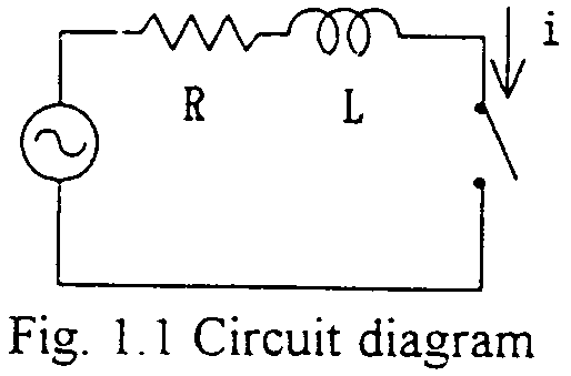
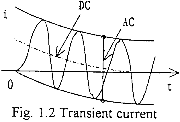
Analytical solution


i=I{sin(wt+a-q)-exp(-R/L)tsin(a-q)} q=tan-1(wL/R),
sin(a-q): DC component at t=0
The steady state short-circuit current is, of course, sinusoidal. But due to the fact that the current through the inductance is CONTINUOUS, so the current begins from ZERO value. Therefore, for the initial time interval, the (decaying) DC component is to be included depending on the short-circuiting point on (the source voltage) wave timing. EMTP calculation data varying the point on wave timings and the results are attached.
For a three phase circuit with X0 (zero sequence reactance) and X1 (positive sequence reactance) seen from the short-circuiting terminals, and phase voltage amplitude E, applying symmetrical component principle, the following short-circuit current amplitudes are obtained for STEADY STATE.
For transient time interval, each phase current has each decaying DC component, the amplitudes of which depend on the point on wave short-circuiting timing.
Steady-state three phase short-circuiting currents
Three phase (grounding) fault
E/X1
Two phase short-circuiting

Two phase grounding fault
E[(1-a)X0-(1-a2)X1]/(2X0X1+X12)
One phase grounding fault
3E/(X0+2X1)
where,

Actual power systems have various capacitances, such as overhead transmission lines, cables, shunt capacitor banks, etc., which introduce further transients. In these cases, digital calculations are recommended. Attached figure show an actual power system short-circuit currents calculated (large scale 550kV system).