Overhead line charging current switchings are carried out rather frequently. --- Switching over, line dropping at maintenance, sound phase when line fault clearing, etc. Restrikes in line charging current breakings cause high overvoltages in the systems. System design permitting the overvoltage corresponds to overinsulation, i.e. expensive construction. Therefore, especially for voltage 66kV and above, "Restrike free" switchings by circuit-breakers are commonly required. For high voltage circuit-breakers, restrike free in charging current switching is a key-word in designing.
In actual transmission lines, very complicated factors such as capacitive and inductive couplings, skin effects, frequency dependent parameters, etc. exist. So, for detailed survey of the switchings, digital calculations are recommended. The examples attached correspond to 550kV, 150km un-loaded line's switchings.
The first case, which is an un-loaded line charging current breaking, shows that in the first phase to clear, the line side residual voltage is enhanced by the capacitive coupling of the rest two phase. Thus the peak recovery voltage in the first pole to clear of the circuit-breaker is 1041kV, which is 2.32 p.u. of the source voltage.
In the second case, where the clearing of the originally second pole to clear is delayed due to the scattering of the contact separation timings, much more high enhancement is introduced and the peak recovery voltage is 1259kV, ie. 2.8 p.u.
In the third example, "Reclosing" is demonstrated. In overhead transmission lines, for keeping better power supply service, (high speed) auto reclosing is applied. A faulted line is opened and after a certain time interval enough to the fault arc quenching, the line is closed. For the sound phase(s) in case of one or two phase fault, the phenomena are similar to a restrike. In the case shown in the example, an overvoltage of 4.2 p.u. maximum is created. To suppress the reclosing over voltages, resistor insertion method is applied. In the example with 1000W of resistor inserted for 10 ms before the main contact closing, the overvoltage is well suppressed up to 1.6 p.u.
Supplement --- Secondary arc quenching in single phase reclosing
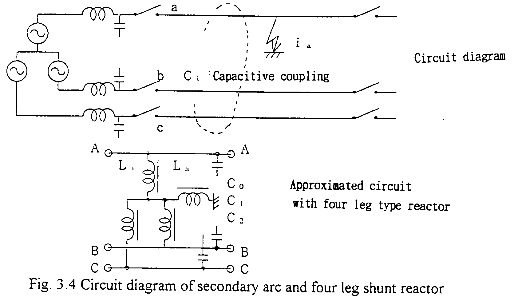
In high voltage and extra-high voltage transmission systems for the purpose to keep power supply as much, in case of one line fault, only faulted phase's line is switched off by the both ends. The fault arc, hopefully, is quenched and the insulation will recover. Then a successful reclosing will be expected. Nevertheless, during the time interval of switched off, small arc (Secondary arc) current may last due to the capacitive coupling from the rest two sound phases. The higher the voltage is and the longer the line is, the secondary arc current is higher and more difficult to quench.
For the purpose to cancel the arc current to establish the insulation, so called, four leg type shunt reactors are applied.
Assuming the voltages and currents along the line arc constant due to low (power) frequency of the phenomena, and regarding the voltages and currents at the fault location, the following equations can be introduced.:

where,Z0=(jS0+1/jX0),Z1=Z2= I/(jS1+1/jX1) and these parameters and values correspond to ones regarding seen from the faulted location.
For the case of Z0 = Zl, from the above equations, we can have iu = I0+I1+I2 = 0, i.e. the secondary arc current is zero. Introducing four leg type shunt reactor connected parallel to the line, by which the system X0 can be controlled by adjusting the neutral to ground reactor, these conditions can be approximated.
Four leg type shunt reactors are useful means to establish successful single phase reclosing in high and extra-high voltage long transmission lines. Many are installed in foreign systems but none in Japan. See Fig. 3.4
