Relatively low reactive currents, such as, energizing shunt reactors, energizing no-load or shunt-reactor loaded transformers, or currents of starting motors, are called as "Inductive currents." Such currents, the magnitudes of which are in the order of from several Amps to several hundred Amps, are very likely to be chopped (forced current zero) before the prospective current zeros of AC. While chopping an inductive current, magnetic energy is, firstly, trapped in the inductance and, then, transfers to electrostatic energy in the capacitance near by, creating an over-voltage across the capacitance terminals. Since many years ago, many insulation troubles due the over-voltages by inductive current breakings have been reported.
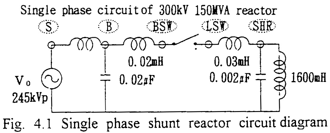
As a typical example, phenomena while breaking a shunt reactor current are take up. Fig. 4.1 shows a single phase circuit diagram.

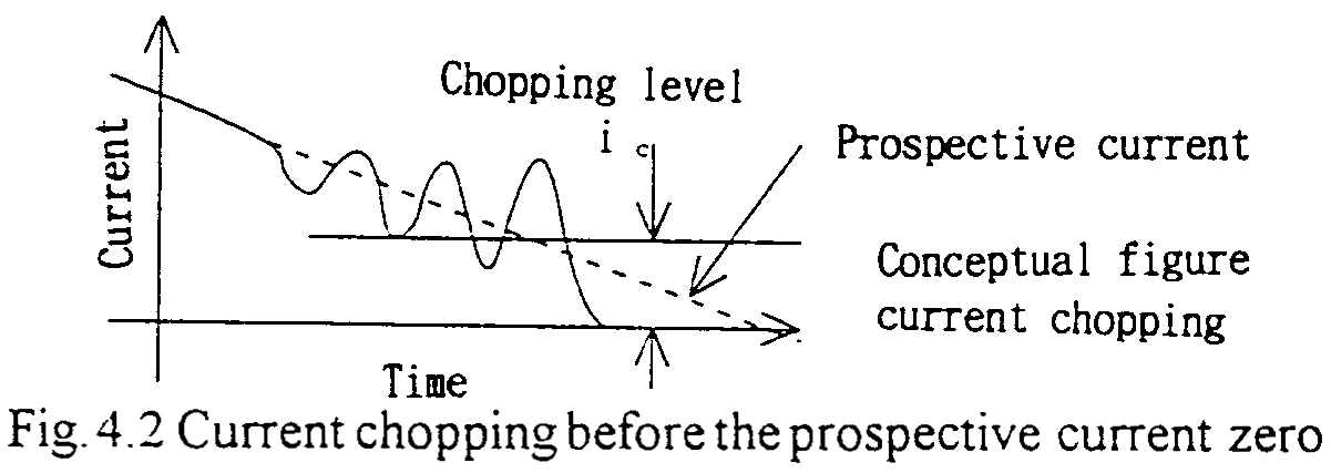
After the contact separation of a circuit-breaker, and while the current approaching the prospective (inherent) current zero, due to the interaction between the circuit elements and the negative V-I characteristics (with various time constants) of the circuit-breaker's arc, (negative characteristics correspond to creating energy) the current begins to oscillate, as shown in Fig. 4.2. When the oscillating wave of the current touches the zero line, the current can be interrupted as shown in the previous chapter as AC current breaking principle. The frequency of the oscillation is very high, such as several hundred kHz, so by oscillogram of usual resolution, the current looks to be chopped instantaneously.

At the instant of the current chopping, the magnetic energy in the inductance and the electrostatic energy in the capacitance are trapped in the load side of the circuit-breaker shown in the Fig. 4.1. When the total energy is converted to the electrostatic one in the capacitance, the highest overvoltage appears as shown in the attached Figures. The following equation is applicable.:(See Appendix 4.1)
Relatively low reactive currents, such as, energizing shunt reactors, energizing no-load or shunt-reactor loaded transformers, or currents of starting motors, are called as "Inductive currents." Such currents, the magnitudes of which are in the order of from several Amps to several hundred Amps, are very likely to be chopped (forced current zero) before the prospective current zeros of AC. While chopping an inductive current, magnetic energy is, firstly, trapped in the inductance and, then, transfers to electrostatic energy in the capacitance near by, creating an over-voltage across the capacitance terminals. Since many years ago, many insulation troubles due the over-voltages by inductive current breakings have been reported.
As a typical example, phenomena while breaking a shunt reactor current are take up. Fig. 4.1 shows a single phase circuit diagram.
After the contact separation of a circuit-breaker, and while the current approaching the prospective (inherent) current zero, due to the interaction between the circuit elements and the negative V-I characteristics (with various time constants) of the circuit-breaker's arc, (negative characteristics correspond to creating energy) the current begins to oscillate, as shown in Fig. 4.2. When the oscillating wave of the current touches the zero line, the current can be interrupted as shown in the previous chapter as AC current breaking principle. The frequency of the oscillation is very high, such as several hundred kHz, so by oscillogram of usual resolution, the current looks to be chopped instantaneously.
At the instant of the current chopping, the magnetic energy in the inductance and the electrostatic energy in the capacitance are trapped in the load side of the circuit-breaker shown in the Fig. 4.1. When the total energy is converted to the electrostatic one in the capacitance, the highest overvoltage appears as shown in the attached Figures. The following equation is applicable.:(See Appendix 4.1)

- where, V: Maximum overvoltage, ic: Chopped level, V0: Source voltage peak
Contact separation of the circuit-breaker is introduced randomly on the point on wave of the breaking (inductive) current. Occasionally the current interruption occurs when the contact gap is short, i.e., just after the contact separation with very short arcing time. For such circumstance "Re-ignition" is inevitable and the maximum reignition voltage can be the highest chopping overvoltage. (Reignition means re-establishment of arc between the contacts just after the current interruption.) At the instant of the reignition, the voltage across the reactor oscillate with extremely high frequency, such as several hundred kHz. By such rapid voltage change, the voltage stress along the reactor winding is no more linear due to the capacitances between the winding to ground. Especially for a several turns from the entrance terminal, the stress is extremely severe. See appendix 4.4. As for the stress, not only the amplitude of the overvoltage but also the rate of change are important. The latter can not be suppressed by a surge arrester. Reignition can not be avoided so, for designing shunt reactor insulations, this stress should be considered with great care. Sometimes, contact separation timing synchronizing systems in order to avoid very short arcing times are applied for the highest reliability.
At the reignition, high amplitude (maximum several kA) and high frequency (several hundred kHz) of current flows in the circuit-breaker. The transient current is damped quickly and then transfers to AC inductive current. After the damping the current can be re-interrupted with farther high trapped energy. The energy may create further high overvoltage which may introduce repetitive (multiple) reignitions. The phenomena is shown in Appendix 4.3. Even though such phenomena do not occur frequently, multiple reignition during breaking inductive current is the enormous condition and should be avoided. Various kinds of means are under consideration today, and above mentioned synchronous contact separation control system is thought to be best.