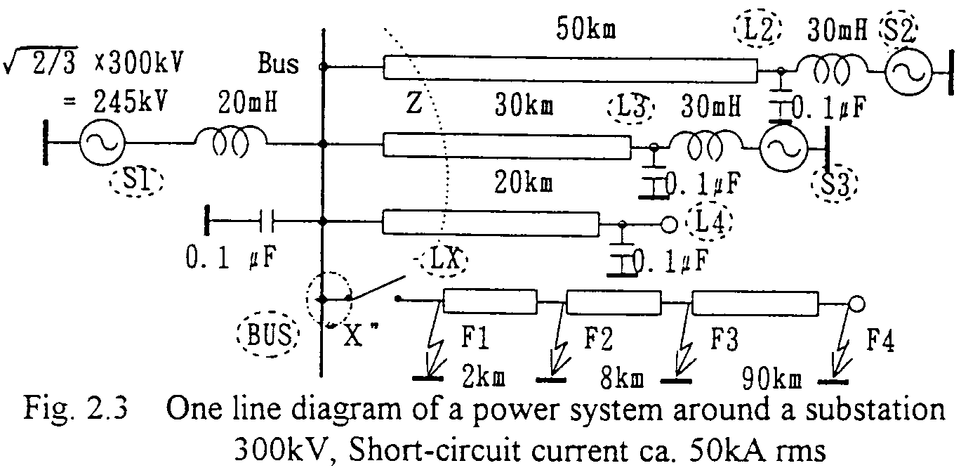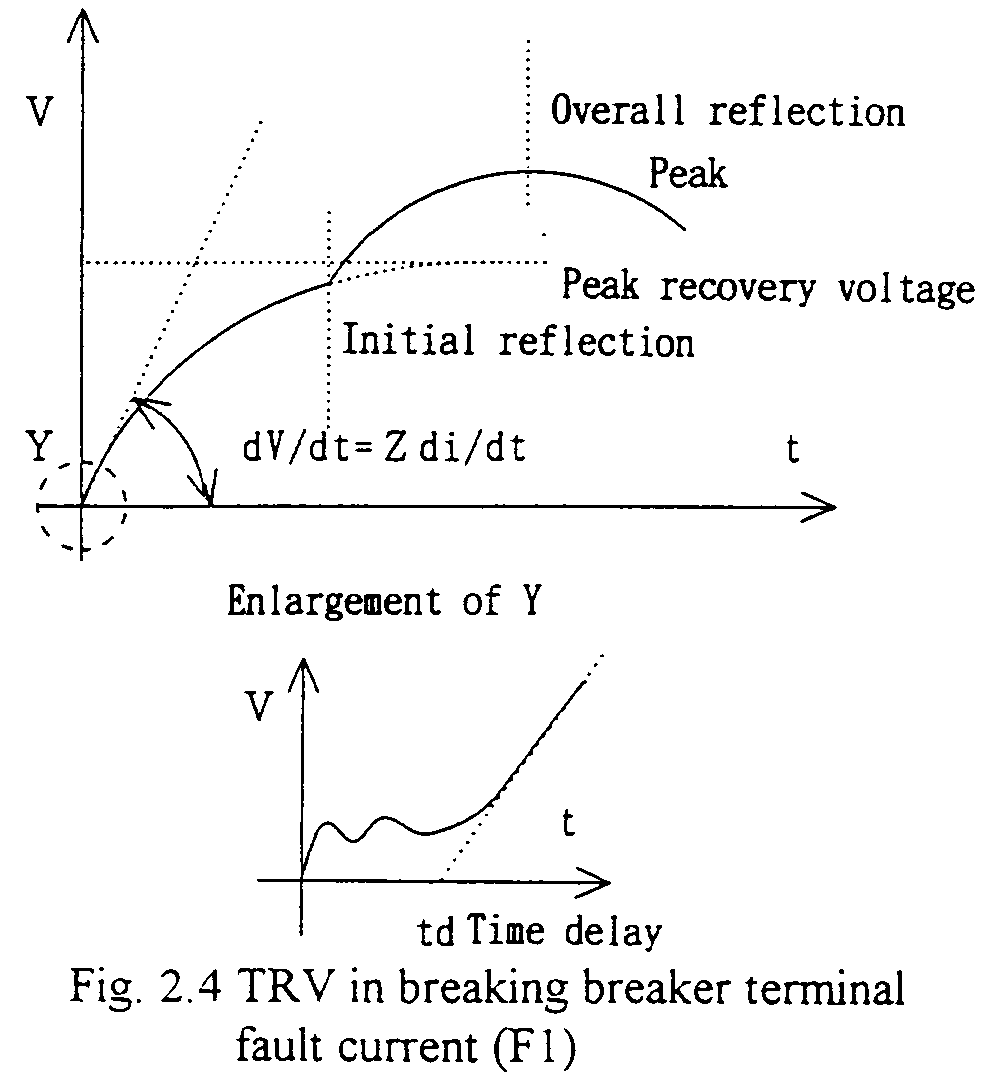
Fig. 2.3 shows a simplified one line diagram of an electric power system around a certain substation. Generally, basic phenomena for TRV can be considered applying such simplified diagram. For three phase circuits, see the following Sub-section.
For considering some typical short-circuit current breakings, fault points F1, F2,---- F4 are introduced.
-
F1 : Breaker terminal fault
F2, F3: Short-line fault
F4: (Long) line fault
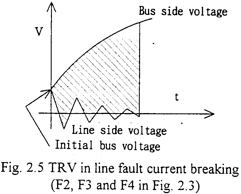
In case F2, F3 and F4 (line faults), also current injection principle is applicable, and positive and negative polarities of currents are injected from the both side terminals of the circuit-breaker. Both side currents produce both side voltages and the sum of them is the TRV across the terminals of the circuit-breaker. As for the voltage potentials to ground at the terminals, initial condition(s) shall be introduced, and also (a) or (b) in Fig.2.2 is to be considered.

Fig. 2.5 shows a typical TRV in breaking (short) line fault current. The voltage across the terminals corresponds to the shaded part.
