5. Modeling transmission lines, cables and transformers
5.2 Cables
Electromagnetic waves inside of a cable (between the core and the sheath) and outside are different, mainly due to the different value of
permittivities (dielectric constants). For instance, the velocities of which are,:
Inside ---- in the order of 150 m/ms
Outside --- in the order of 250 --- 300 m/ms
Therefore, especially for calculating transients of high frequency components, both the inside and the outside should be correctly modeled. As the most simple way, general distributed parameter circuit is applicable, but modeling only the inside. So this method is valid when the sheath voltage is negligible (rigidly grounded). Combination of outside and inside coupled with ideal transformers is possible (see attached Appendix) but today's EMTP sub-routine "Cable Constants" is generally more convenient which can, directly, model various kinds of configurations. From the geometrical configuration's point of view, the following cable system(s) are applicable in the sub-routine.:
Multi phase cable system without enclosing pipe
Features:
Applicable to cables located in the air or underground.
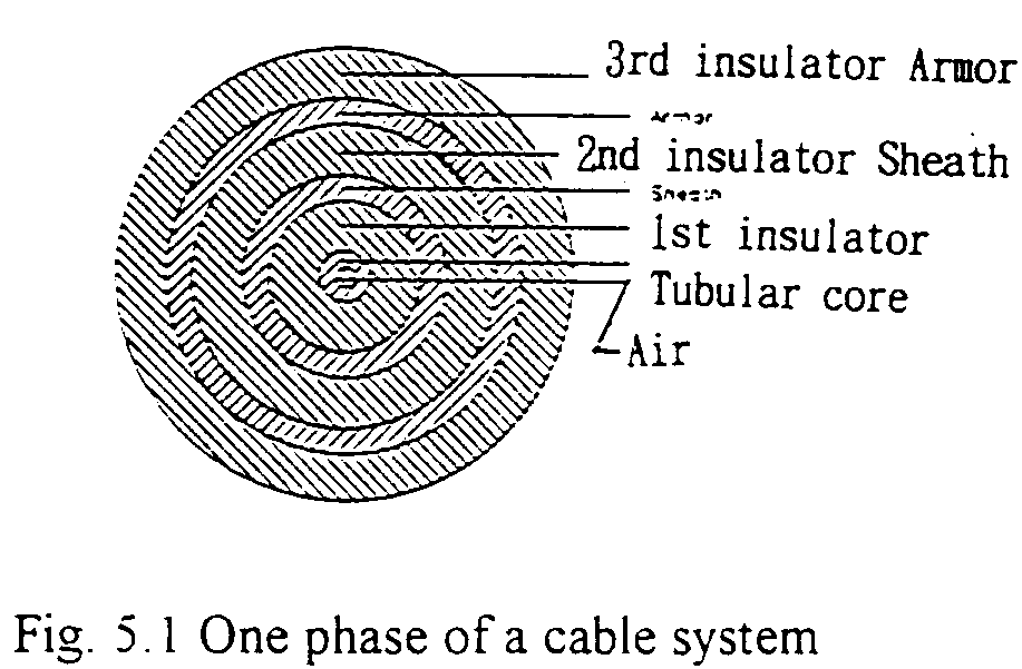
Geometry of each cable is shown in Fig. 5.1.
Enclosing duct can not be modeled.
Excluding 2nd insulator, armor or 3rd insulator is possible.
For directly burying type.
Mostly applicable to single phase model.

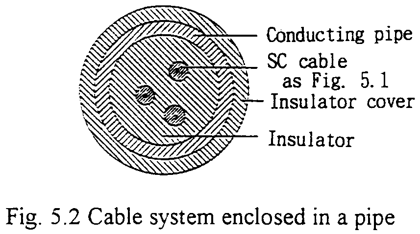
Multi phase Cable system enclosed by a conducting pipe
Features:
The conducting pipe can be of very low conductive material such as concrete.
Each cable can be as shown in Fig. 5.1.
Applicable to multi-phase installation in a duct.

From electrical point of view like transmission lines, the followings are applicable.:
(Multi stage) lumped PI model
Features:
Highly reliable.
Should be careful of the effect the high capacitances connected to the both ends.
For relatively low frequency of phenomena.
Mostly for power frequency.
Automatic cross-bonding model is possible.
Distributed parameter circuit model
Features:
Relatively good experiences.
For limited range of frequency.
Frequency dependent model -- Semlyen model
Features:
In principle, for wide range of frequency
Poor experiences, especially for low frequency of range.
An example is attached simulating a single cable system, the dimension of which corresponds to measuring purpose one.
This page is based on Prof. E.Haginomori's lectures
in Tokyo Institute of Technology, and edited by Japanese ATP User Group.
Copyright (C) Eiichi Haginomori and Japanese ATP User Group.

