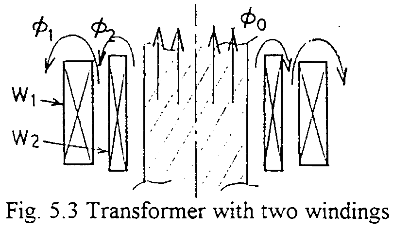
For the transformer with two windings as shown in Fig. 5.3, the following equations are obtained.:


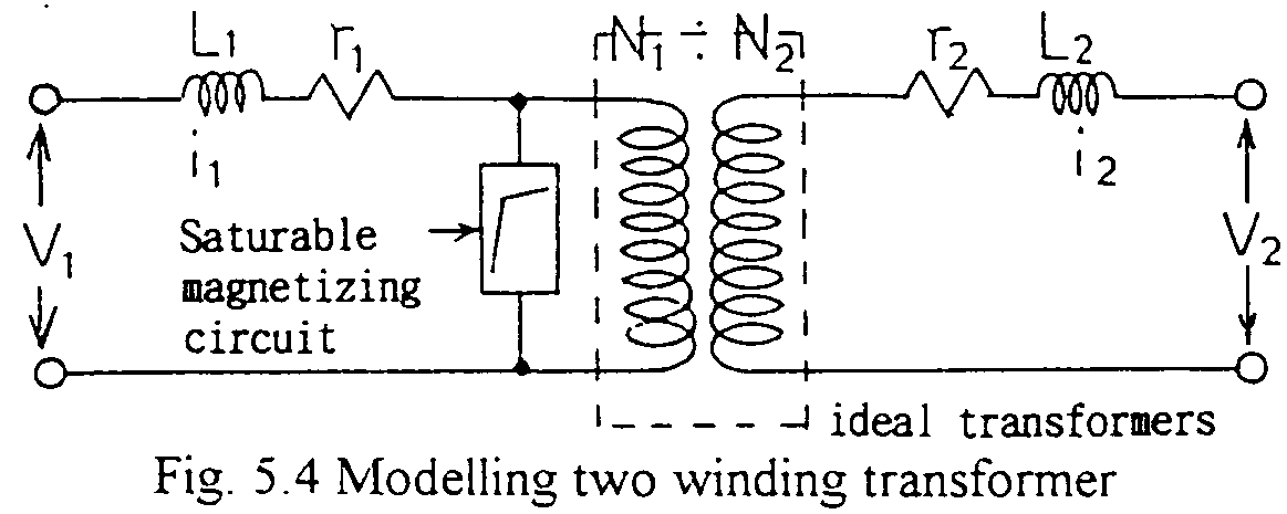
The equation corresponds to the circuit with an ideal transformer shown in Fig. 5.4. Saturable magnetizing circuit can be connected any side of the ideal transformer. Such modeling can be easily applied in EMTP introducing "TRANSFORMER". (See attached example) Ll and L2 are called leakage inductances corresponding to the respective flux linkages, and rl and r2 are resistances of the windings.

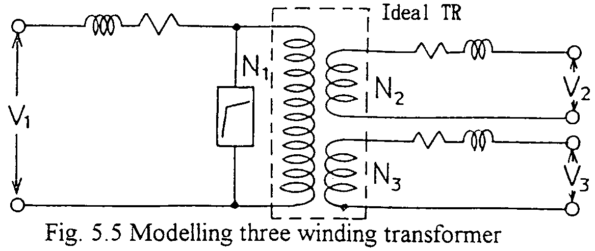
A three winding transformer is modeled as Fig. 5.5. The model corresponds to the assumption that each couple of windings has a just common flux. Actually, winding 1 and winding 2 may not have quite the same common flux of winding 2 and winding 3. But for general cases of actual power transformers, the model is applicable with enough accuracy.

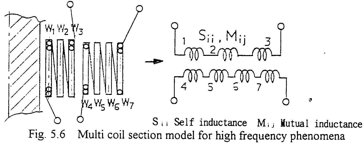
Transformer models above mentioned are applicable in the frequency range of up to a few or several kHz. In higher frequency range, such as higher than 10kHz, or for lightning or switching impulse surges, voltage distribution in one winding is no more linear due to various capacitances to ground and within the winding (due to internal resonance(s)). For such high frequency of voltages, therefore, one winding should be modeled in more than several sections. Each section has self inductance and mutual ones to others. So the total windings including primary, secondary, etc. are represented by a inductance matrix. At the same time the performance of the iron core is to be noted. For high frequency of phenomena almost no flux exists within the core. Sometimes for the frequency range of lightning impulses, models where the iron cores are replaced by air are appropriate. An example is shown in Fig. 5.6.

In the figure, the primary and the secondary windings are separated three and four sections respectively. Each section has each self inductance and mutual, each other, one which is obtained by electromagnetic calculation. Therefore, the total inductances are represented by a inductance matrix. Such inductance matrix can easily be applied to EMTP calculation.
The inductance matrix is shown below.:

where, Wi is the name of the windings, and Sii and Mij are self- and mutual inductances respectively. Actually in EMTP calculations, each inductance may have series connected resistance. Also Capacitances are connected between terminals of these inductance branches and terminals to ground.