6. Power flows and voltage stabilities in power systems
6.1 Power flows
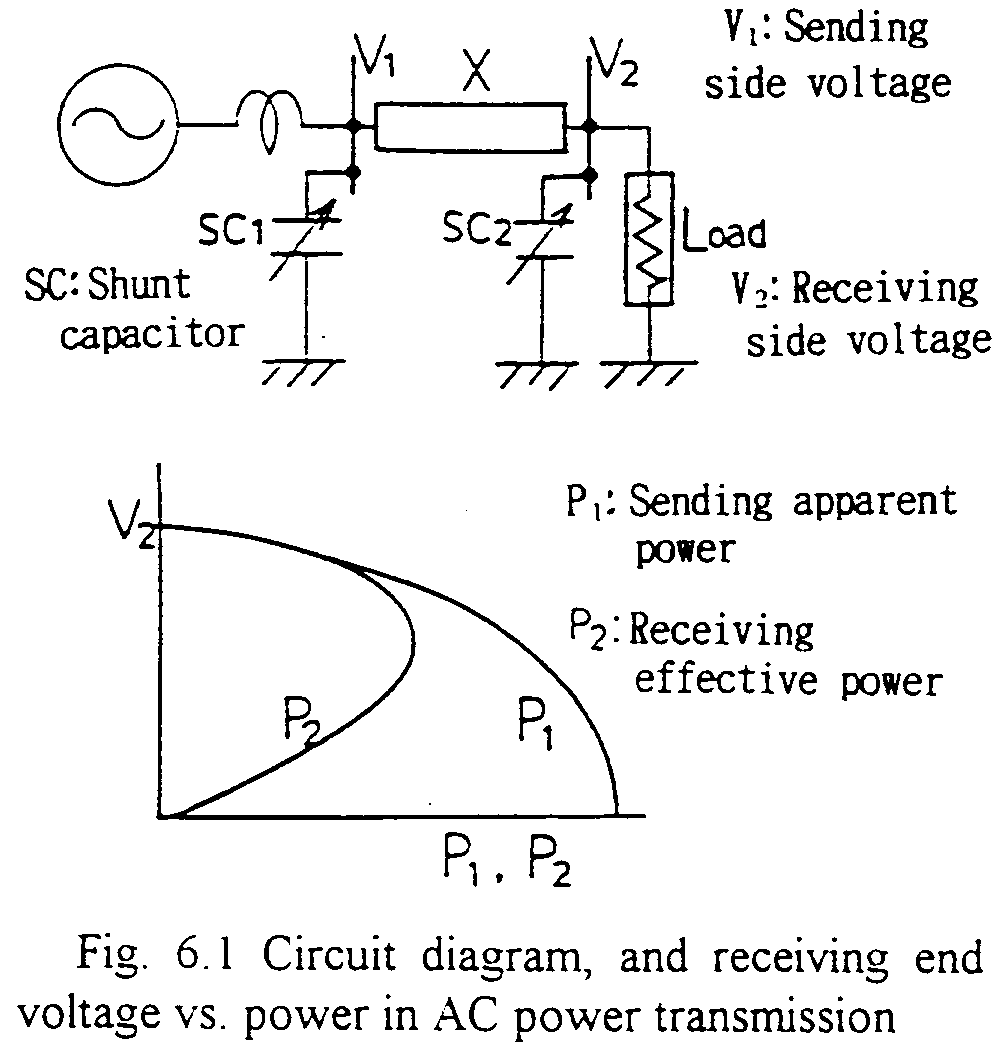
Power flow (sometimes called as tidal flow) phenomenon is, in most simplified single phase case, represented by source side and receiving end voltages coupled by a reactance in between. The transmitting power in the circuit is represented by the following well known formula:
where, V1 and V2 are voltages at sending and receiving ends respectively, and q is the electrical angle difference between the two voltages. X is the reactance of the transmission line etc. It may worth mentioning that the power is proportional to the voltage angle difference with the maximum value at q=p/2. Under heavy power flow condition, the voltage angle of the source is more advanced to that of receiving end. Even though the power factor of the load is high, i.e., an equivalent load resistance is connected to the receiving end, the power factor seen from the sending end may not be so high. The heavier the load is, the lower the power factor is. Fig. 6.1 shows the circuit diagram and Receiving end voltage vs. (real) Power curve.

To increase the power transmitting efficiency, shunt capacitor banks are installed at the sending side which decrease the current by increasing the power factor.
This page is based on Prof. E.Haginomori's lectures
in Tokyo Institute of Technology, and edited by Japanese ATP User Group.
Copyright (C) Eiichi Haginomori and Japanese ATP User Group.
