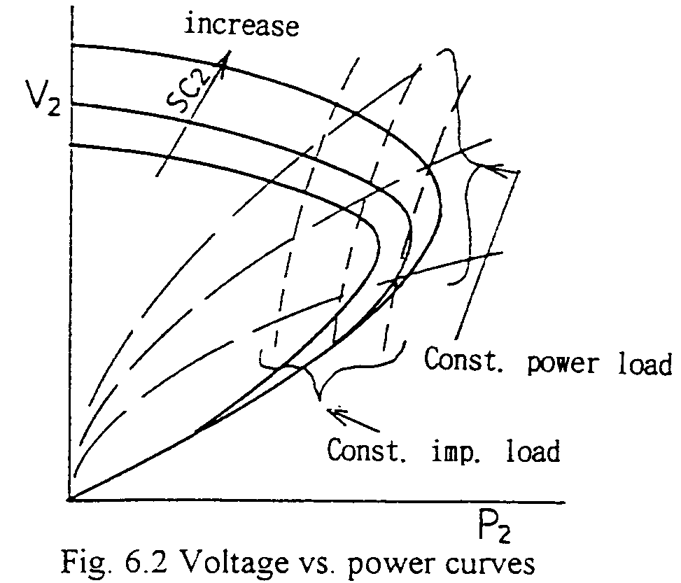
For load circuits, there exist two kinds of circuits, i.e. constant impedance one and constant power one. The former are typically lamps or heaters. The latter are induction motors, power electronics facilities, etc., the portion of which to the total load is increasing lately. In Fig. 6.2, also the voltage vs. load curves are drawn. The crossing manner (angle) with the voltage curve is different in two kinds of loads. Constant power load corresponds to unstable conditions, i.e. the rate of change of voltage is higher for higher power condition. Introducing transformer tap changing, even the constant impedance load becomes also constant power like characteristic.

For increasing the critical transmissible power, two kinds of facilities are applied. ---- Series capacitor and Shunt capacitor (bank). ----
The effect of the former is doubtless. In the formula before shown, the value of the reactance X is reduced and power P is increased for the same q. Applying a series capacitor, the reactance value of which is a portion of that of the relevant transmission line, the resonant frequency of the series connected reactance and capacitance is lower than the power frequency. The situation may introduce an unstable condition to the relevant power system, so great care should be taken. In Japan, only a few have been introduced, on the other hands a great number in foreign countries.
The effect of shunt capacitors is also shown in Fig. 6.2. Care should be taken that, increasing the shunt capacitor bank capacity, the voltage in no load or light load condition may be too high, and for heavier load condition, the rate of change of the voltage is higher --- may be more unstable.
From Fig. 6.2, it's clear that for heavier load condition, increasing the capacitor bank capacity, higher transmittable power condition can be obtained, though unstable as mentioned above. The figure corresponds to steady state conditions. Actually, the increase of the load may rather rapidly occurs. In such situation, also quick shunt capacitor insertion may not be able to follow immediately, and the voltage may not be able to be kept. ---- resulting in Voltage Collapse or Black out ---- Recently in some countries including Japan, such power system failures have been experienced. One of the important reasons to introduce SVCs and SVGs is to introduce the possibility for such quick controlling of compensation.
In the appendix attached, some calculations are shown regarding the transmission voltage stability. As a typical example of constant power load circuit, an induction machine is introduced. By lowering the voltage, also lowering the flux in the machine, then the current increase in order to keep the torque with a little increasing of the slip value.
In case of constant impedance load only, the voltage is stabilized at once after the additional load.
In case of induction machine load, where the load value beforehand has been critical, by the increase of a little additional load, the voltage lowered gradually and finally collapsed.
Series or Shunt (parallel) capacitor introduce significant effect.
Notice for induction machine applications
It can be said generally that induction machines are quasi constant power loads. If power system voltage is lower than the rated voltage of the induction machine, the current increases by almost inversely proportional to the voltage. Great care should be taken for overheat of the machine.