In a three phase bridge rectifier circuit as shown in Fig. 8.1, the theoretical (with idealized circuit parameters) harmonic components are:

For eliminating these harmonic components in the AC side, which is the general requirement of the power utilities, series resonance filters for these harmonic component frequencies are applied. Due to the rather wide band range of the harmonic components, the filter characteristics spectrums themselves can not be so sharp. That means, it is essential that the capacitance values in the series resonance circuits can not to be low to obtain rather high admittance filter characteristics covering the wide band range.
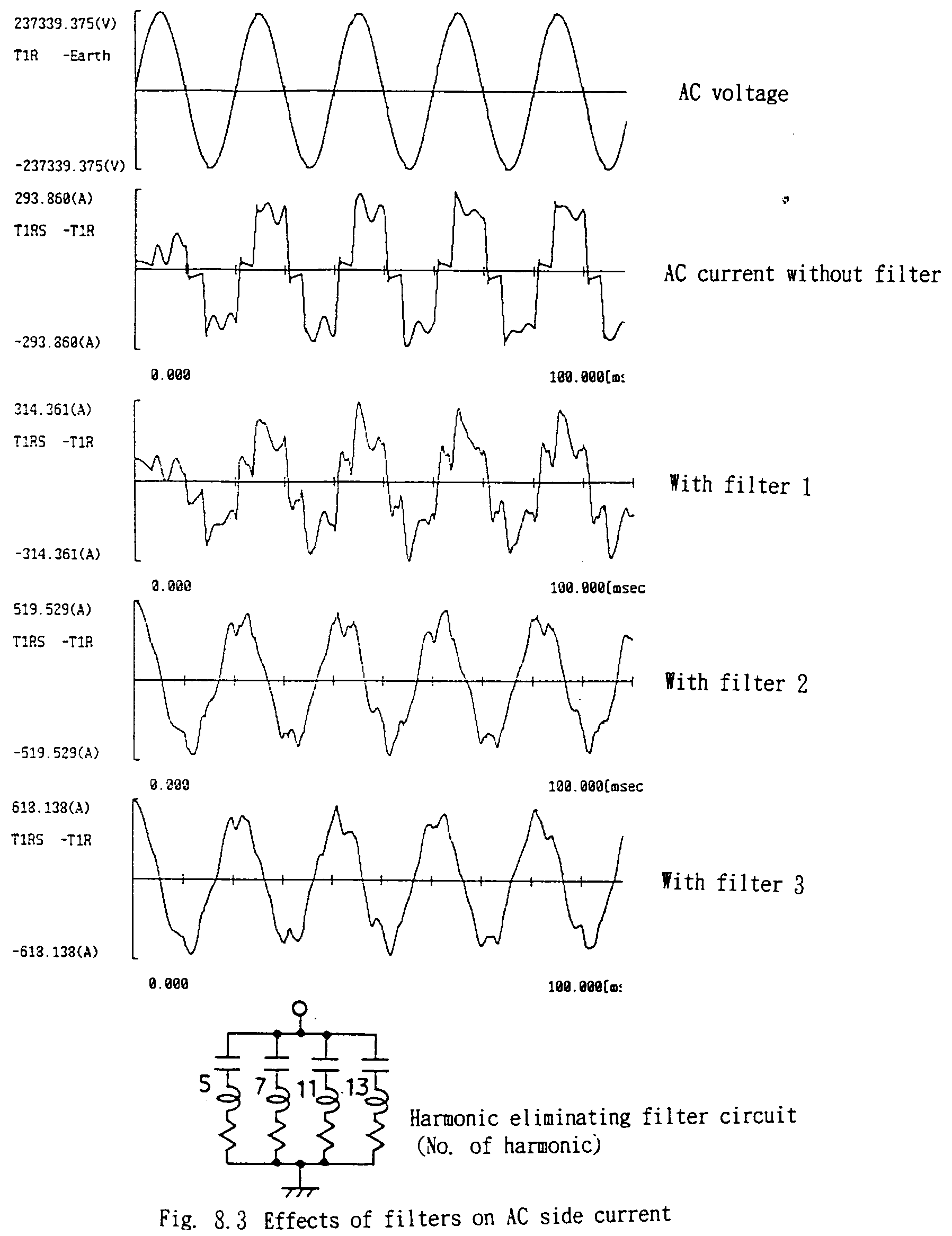
As trials, let's connect the following filters (R,L, C connected in series) between the lines and ground of the primary side of the transformer.
|
|
|
AC side current wave forms with these filters are shown in Fig. 8.3. With filter 1, the resonance frequencies of which are sharply tuned to the theoretical harmonics but the admittances are not so high due to the smaller capacitance values, no significant improvement in the AC side current wave form is found, or even worse. For filter 2, the capacitance values for 5th and 7th harmonies are increased by 10 times, significant improvements are shown. Filter 3, the capacitances also for 11th and 13th harmonics are increased, further more improvements are observed.
These conditions are much depend on the source side circuit parameters, i.e., comparison between the source and the filter's admittances, therefore, calculations including the detailed source circuit parameters are necessary for designing the filters.

ATP Data Source for "Without filter" case
ATP Data Source for "With filter1" case
ATP Data Source for "With filter2" case
ATP Data Source for "With filter3" case