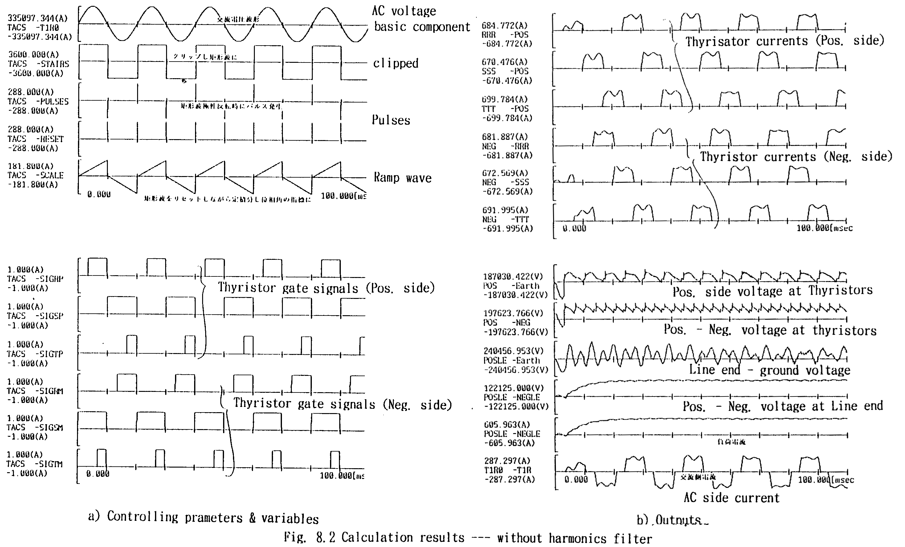
Fig. 8.2 shows the calculation results ----control parameters, gate signals, current of each valve, currents and voltages in AC and DC sides. The AC side current is much distorted --- involving large amount of harmonics. In Appendix 8.2, the Fourier spectrum data of the current wave form are attached. In actual rectifier systems, for eliminating harmonies in both AC and DC sides, multi-phase (6-phase, 12phase or more) rectifier systems have been applied. But in this chapter, as a simple example, filters for three-phase rectifier system is discussed.
