In a certain electric circuit, while breaking short-circuit currents, TRVs (Transient Recovery Voltages) appear in various manner depending on the asymmetry rate of the short-circuit breaking currents (See chapter 1 and 2. and also Appendix 11.1). In IEC (International Electrotechnical Commission) and JEC (Japanese Electrotechnical Committee) standards for circuit breakers, the rated TRVs are specified corresponding to breaking symmetrical currents (With zero DC component). In actual systems or direct short circuit breaking test circuits where short circuit currents and TRVs are supplied from common sources, TRVs by asymmetrical short circuit current breakings are automatically adjusted appropriately. So, attention is to be paid only for breaking symmetrical currents. While, calculations of TRVs by breaking asymmetrical currents are generally not necessary.
The ratings of today's most high capacity of circuit-breakers in Japan are:
| Rated voltage | 550 kV |
| Rated breaking current | 63 kA |
In asymmetrical current breaking tests by synthetic test method, also the respective TRVs are necessary to be calculated beforehand because adjusted (not automatically) TRVs are to be supplied from the high voltage source. Therefore, calculations TRVs when breaking asymmetrical currents are necessitated.
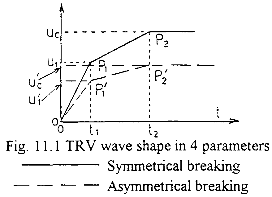
Some attempts had been done before the attached literature. The rated TRVs specified in the standards are represented by three segments as shown in Fig. 11.1 (4-parameter method).

Of cause, the rated TRV wave shape corresponds to breaking symmetrical current. In the preceding attempts, firstly circuit parameters corresponding direct test circuits corresponding to the rated TRV wave shape were introduced. Some approximations were necessitated, and, therefore, plural test circuit diagrams could be introduced. Also, complicated circuit synthesis technique was necessary. Furthermore, plural TRVs for one kind of asymmetrical current breaking condition were obtained depending on the circuit parameters applied. Therefore, standardized method had been wished in, especially, the standard of IEC.
The most important main point of the method talked in this chapter is that the wave shape shown in Fig.11.1, which is composed of three segments, can be represented by a very simple form in Laplace domain. So, simplified, but strict, forms in Laplace domain can be introduced for the calculations of TRVs in breaking asymmetrical currents instead of using complicated, but still approximated, actual circuit diagrams.
Applying cancelling current injection principle shown in Chapter 2, TRV in Laplace domain for symmetrical current breaking is expressed by the following formula.:
-
TRV(s)=I(s)Z(s) ---- (1)
I(s)=w/(s2+w2)

-
A1=u1/sinwt1
A2=(A1sinwt2-uc)/sin{w(t2-t1)}
A3: Will not be used in this chapter
Also for TRVs for asymmetrical currents, wave shapes can be obtained by superimposing injecting asymmetrical current wave shapes with same multiplying factors and time shiftings corresponding to the same circuit. Therefore, for P1', and P2' for asymmetrical currents,:
For P'1(t1,u'1) u'1=I(t1)A1 ---(3)
For P'2(t2,u'c) u'c=I(t2)A1-I(t2-t1)A2 ---(4)
where i(t) is asymmetrical injecting current:
i(t)=sin(wt+a-q)-e-(R/L)tsin(a-q)
q=tan-1(wL/R) --- Power factor angle of the circuit
sin(a-f) - - - Asymmetry at current zero
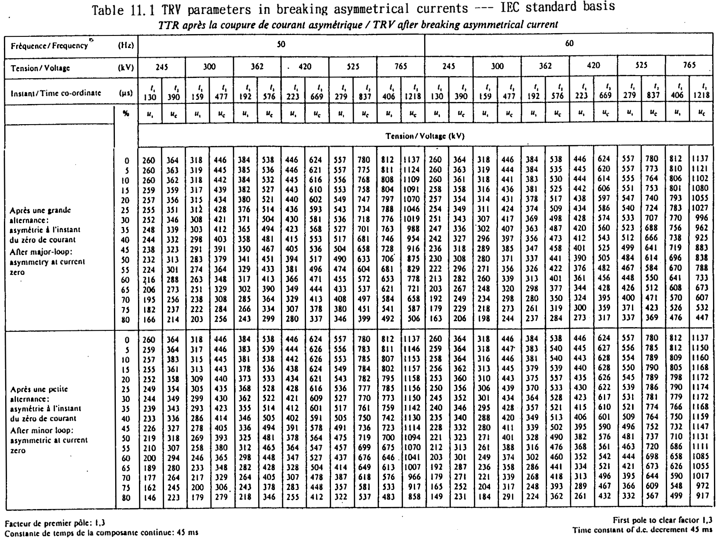
In the standards, it is specified that f = 1.50 rad. and 1.51 rad. for 50 Hz and 60 Hz respectively. By the equations (2) --- (4), TRVs for asymmetrical current breakings are calculated. For IEC standard, see Table 11.1 which has been introduced to actual standard. For JEC standard, see attached literature which is under consideration to be introduced.
