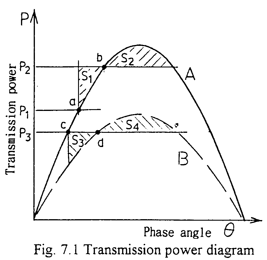
As shown in the previous chapter, the transmission power of a system is given as:


As an example, in the figure, the system is transmitting power P1 corresponding to point a. Then suddenly the mechanical input to the generator is raised to P2. The steady state condition corresponds to point b, and the angle is to be increase (the generator is accelerated). During the angle increase, the energy corresponding to S1 is excesses and the machine angle over-swings. In case:
- S1 <S2,
In the next example, the system is transmitting P3, and is suddenly the transmitting capacity curve is switched from A to B shown in the diagram, such as one circuit of a double circuited transmission line is dropped. Likewise as the previous case, the energy corresponding to S3 is excess during the transition from c to d which is the steady state point alter the switching over. Then, the generator's angle over swings and the equation:
- S3<S4
For another kinds of system disturbances, such as short-circuiting faults, load capacity changing, generator outputs, etc., the corresponding area shall be calculated separately. In this method, the power system is represented by the steady state parameters. Therefore, controlling of the generator such as AVR (Automatic Voltage Regulator), PSS (Power System Stabilizer) or damping effects in the system for the angle swinging can not be introduced. So this is used for only rough estimation of the system stability.