In Fig. 7.5, a few examples of dynamic torques during short-circuiting are shown. The calculations were done applying a detailed generator equation (Park model equation) for a 500MVA, two pole machine which is connected to the low voltage side of a step-up transformer.
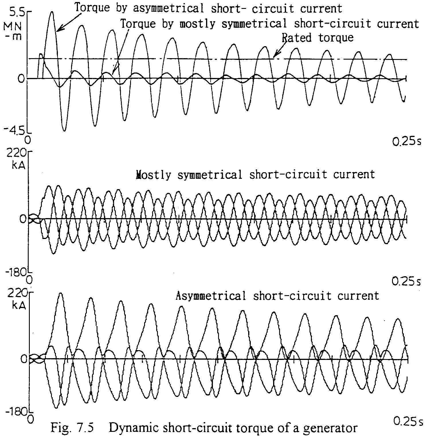
The high voltage side of the transformer is short-circuited under line charging current supplying. The point on wave timing of short-circuiting is varied for each of the three phases so as to produce relatively high or low DC components in the short-circuit currents. For high DC components, the torque carve shows high amplitude of swing with the maximum value of three times of the rated torque. With low DC component, also the swing amplitude is lower. From the figure, the torque swing is estimated to be, finally damped to quasi zero. In R.M.S. value based calculations, as mentioned in the previous sub-chapter, only quasi zero (steady state) value is applied. But, especially far the initial transient time interval, quite different phenomena may appear depending on the DC components of the short-circuit current, i.e. the point on wave short-circuiting timing. The condition of almost zero DC component, only which is applied in conventional analysis, is even a quite special case. Therefore, for more accurate calculations or for the case that phenomena in shorter time interval are concerned, true dynamic torque based analysis is to be applied as shown in this sub-chapter. Such analysis is possible applying a high performance power system analyzer or EMTP.
Lately, high speed power system controlling facilities such as SVCs, SVGs or doubly-fed induction machines have been of great interest. Analyses of faster transient is becoming much more Important.
Applying EMTP as the calculation software, power system parameters shown in Fig. 7.2 (same as in the previous sub-chapter), and AVR and PSS block diagram shown in Fig. 7.3, some analyses have been done as shown in the followings.:
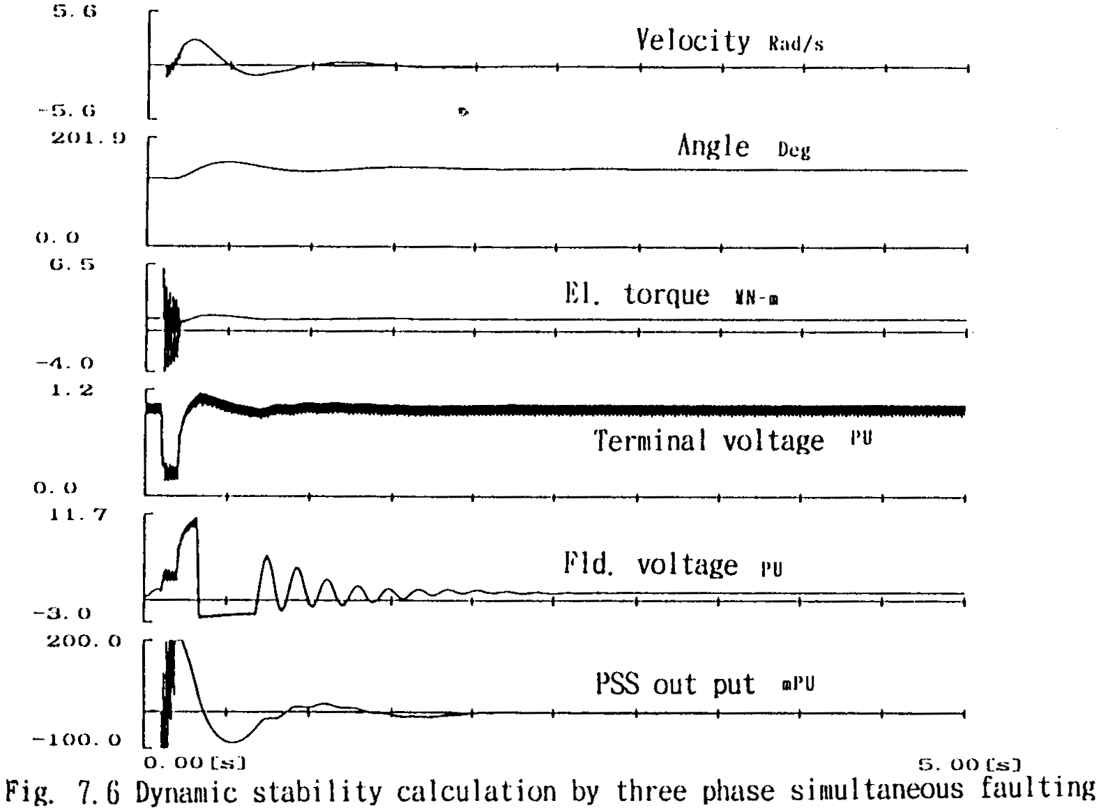
Fig. 7.6 shows the calculation results when three phase simultaneous short-circuiting during 0.1s and 0.2s. The initial power flow calculation can be automatically done applying FIX SOURCE option included in EMTP. The transmitting power quantity is 375 MW same as in the previous sub-chapter (R.M.S. value based calculation). As the most interesting parameter, the maximum swing angle of the generator is only 30 deg. which is far smaller than the previous calculation result which is 75 deg. as shown in Fig. 7.4. The stability of the transmission system might be thought to be higher. But this is not perfectly correct. The generator's electrical torque shows vigorous swing and for the first stage, the generator is even decelerated.
 ATP Data Source
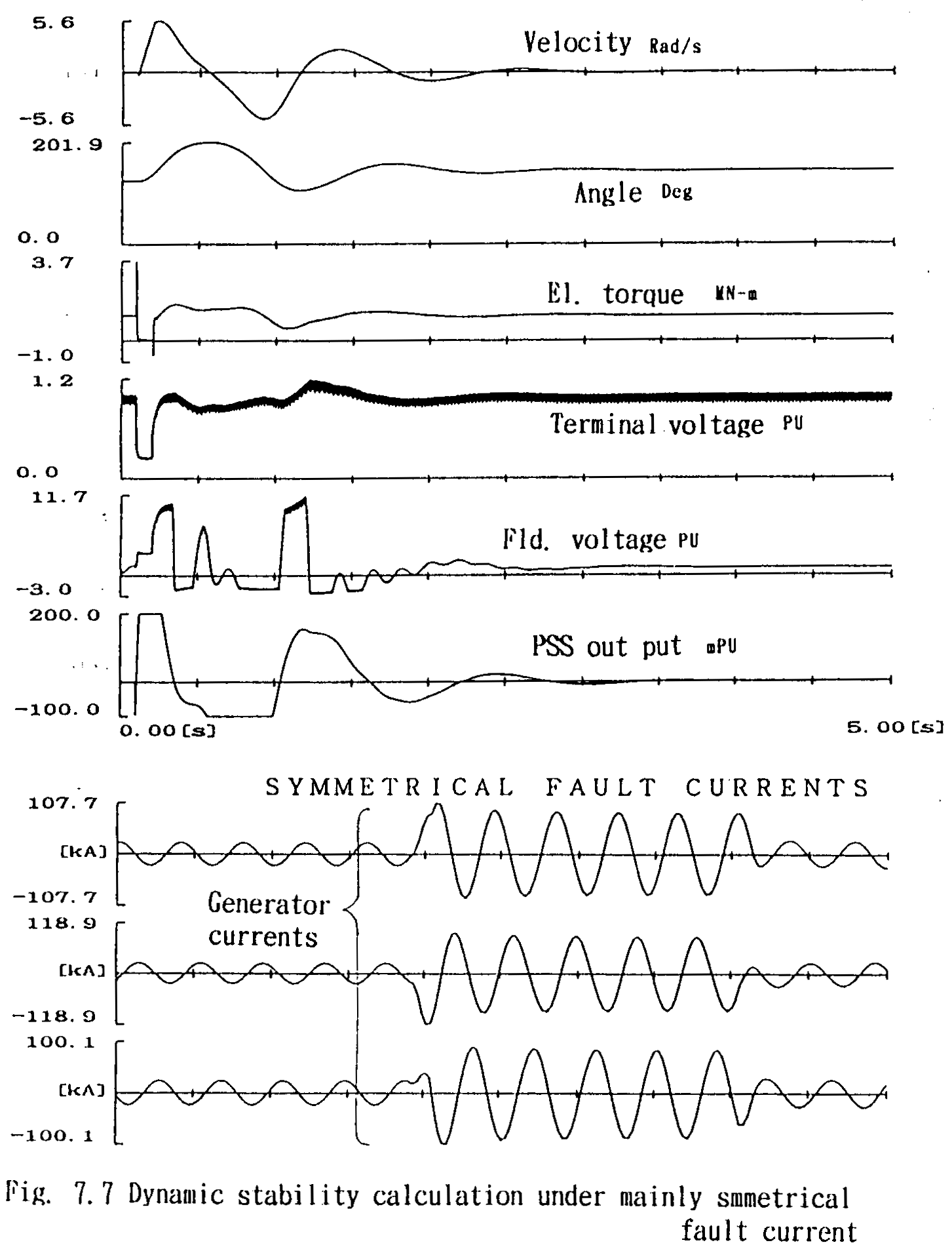
 In the next case, varying the point on wave timing of the grounding fault initiation to seek minimum DC components in the three phase short-circuit currents, calculations are done. A typical result is shown in Fig. 7.7. together with the three phase short-circuit current wave forms. During the short-circuiting time interval, the electrical torque is almost zero. So the angle swing amplitude is ca. 75 deg. which coincides with the result in Fig. 7.4 (R.M.S. value based calculation).
 ATP Data Source
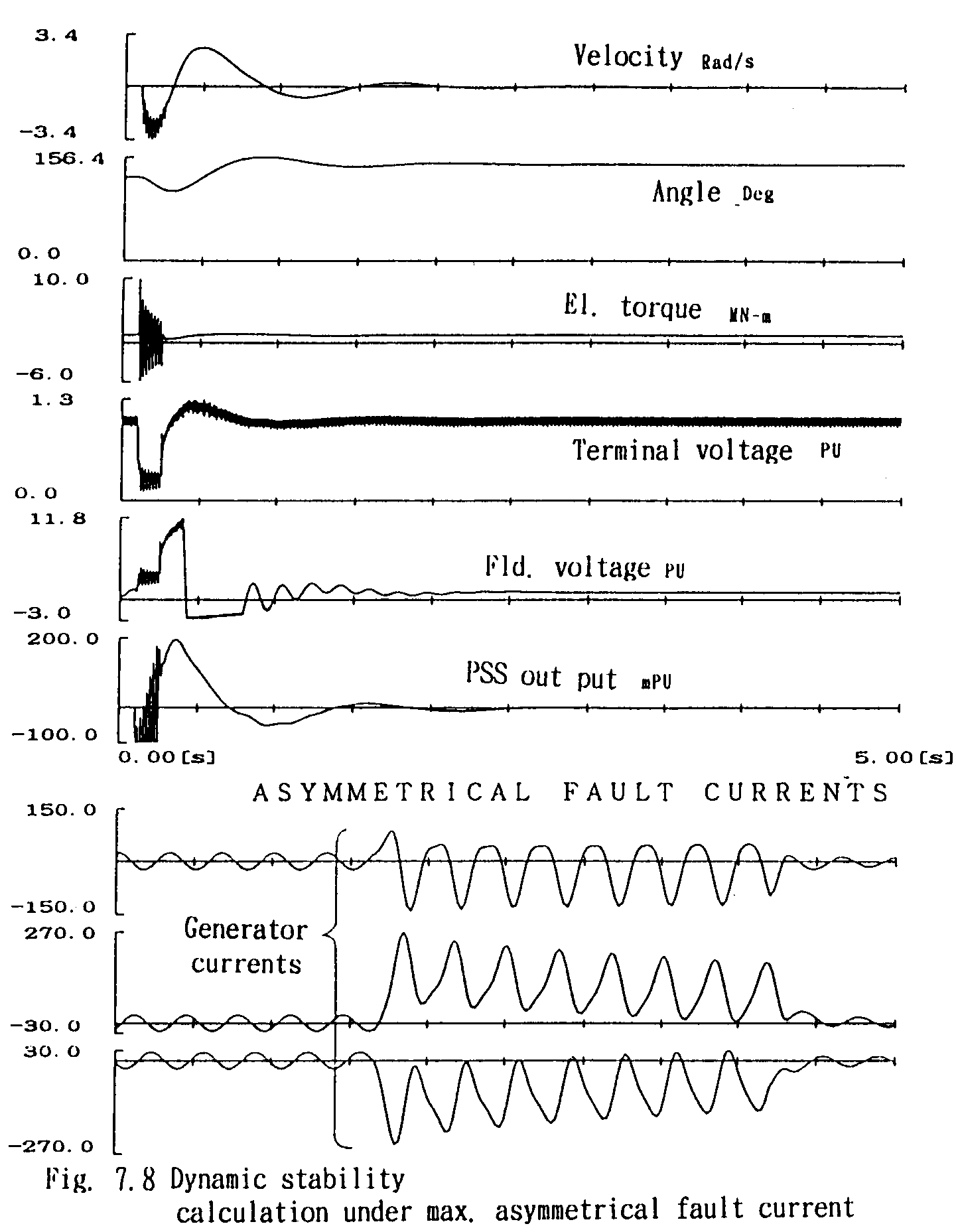
 For another example, Fig. 7.8 shows for maximum DC components in the short-circuit current of the generator together with the current wave forms. The torque swings farther more and during the short-circuiting, the generator much decelerates. Therefore the amplitude of the angle swing is only 29 deg.
 ATP Data Source
 As a conclusion of this sub-chapter, the instantaneous value based calculation coincides with R.M.S. value based one in only the case of negligible DC components in the short-circuit currents. Generally speaking, with certain amount of DC components, less severe results are brought with smaller amplitude of the generator angle swinging.
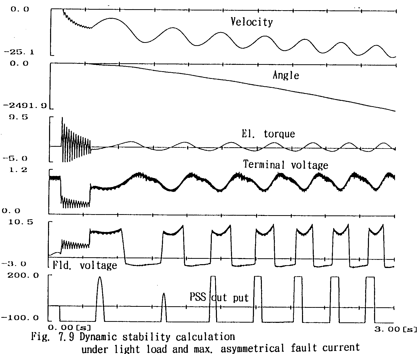
Nevertheless, as the DC components act to decelerate the generator, for cases of small output or minus output such as during pumping, the effect may act to introduce out of step condition in decelerating direction. An example is shown in Fig. 7.8, where, the initial power flow (output of the generator) in less than 10% of the rating, and the short-circuit fault currents have maximum DC components in the three phases. The generator goes to out of step in the decelerating direction.
 ATP Data Source