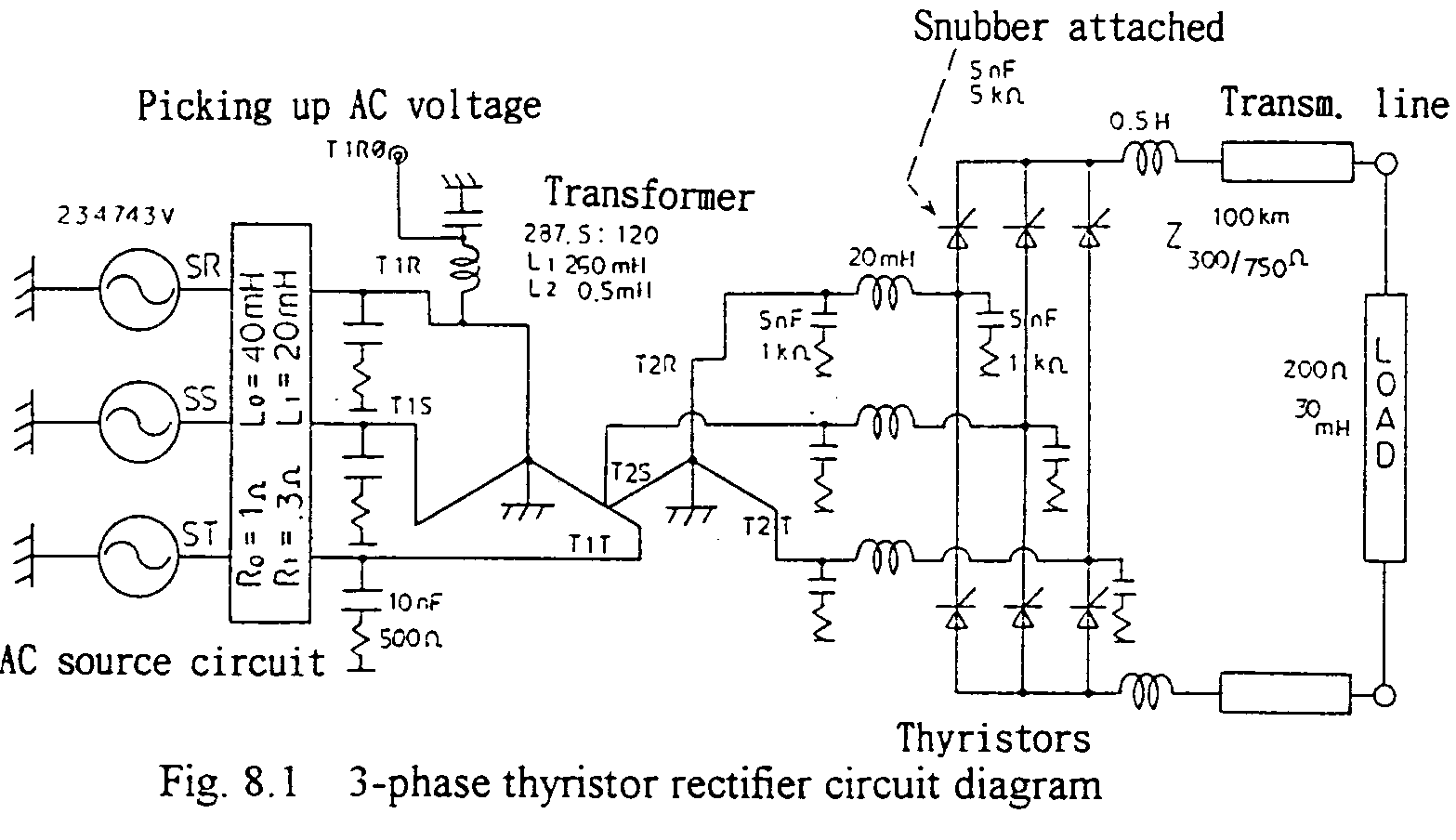
Fig. 8.1 shows the circuit diagram, where, filter circuits are additionally connected in the source side (see section 8.3) and snubbers (not shown in the figure) are connected in parallel to the thyristor elements. AC side three-phase source voltage is, 287.5kVp-p R.M.S. (234.7kVp phase to earth), connected to the transformer through the source impedances. Thyristor gate controlling (electrical) angles are to be on the basis of the AC side voltage wave form, therefore, the mainly fundamental component of which is picked up by the resonance filter. The DC side is connected a transmission line of 100km through DC reactors. The line is terminated by the load circuit.

As the basic signal to control the thyristor firing angle, a saw tooth (ramp) formed wave, the peak value of which is 180 and the period is 10ms, is produced in the controlling system (TACS) on the basis of the AC side voltage fundamental. Using the TACS-originated signal for this is more easy, but not practical in case of disturbances in the source circuit. The secondary side voltage of the transformer is 120kV. EMTP data is shown in Appendix 8.1.