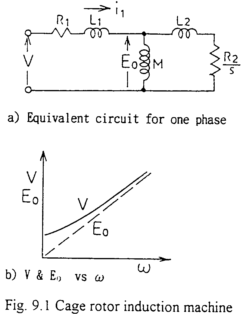
Fig. 9.1 shows an equivalent circuit of an cage rotor induction machine for one phase. For the machine, the following formulae are obtained.:

where, w: angular frequency of the source
ws: angular frequency of slip
Keeping E0/w= constant, then the current I1 and the torque T are constant irrespective of the machine speed, and they are functions of ws. The equations also show that, varying the voltage and frequency of the source, various performances for wide range of the machine speed can be obtained. Exactly speaking, V (motor terminal voltage) and E0 are different especially for low value of the source frequency. In the case very accurate control is required, the correction shall be introduced (see Fig. 9.1 b)).