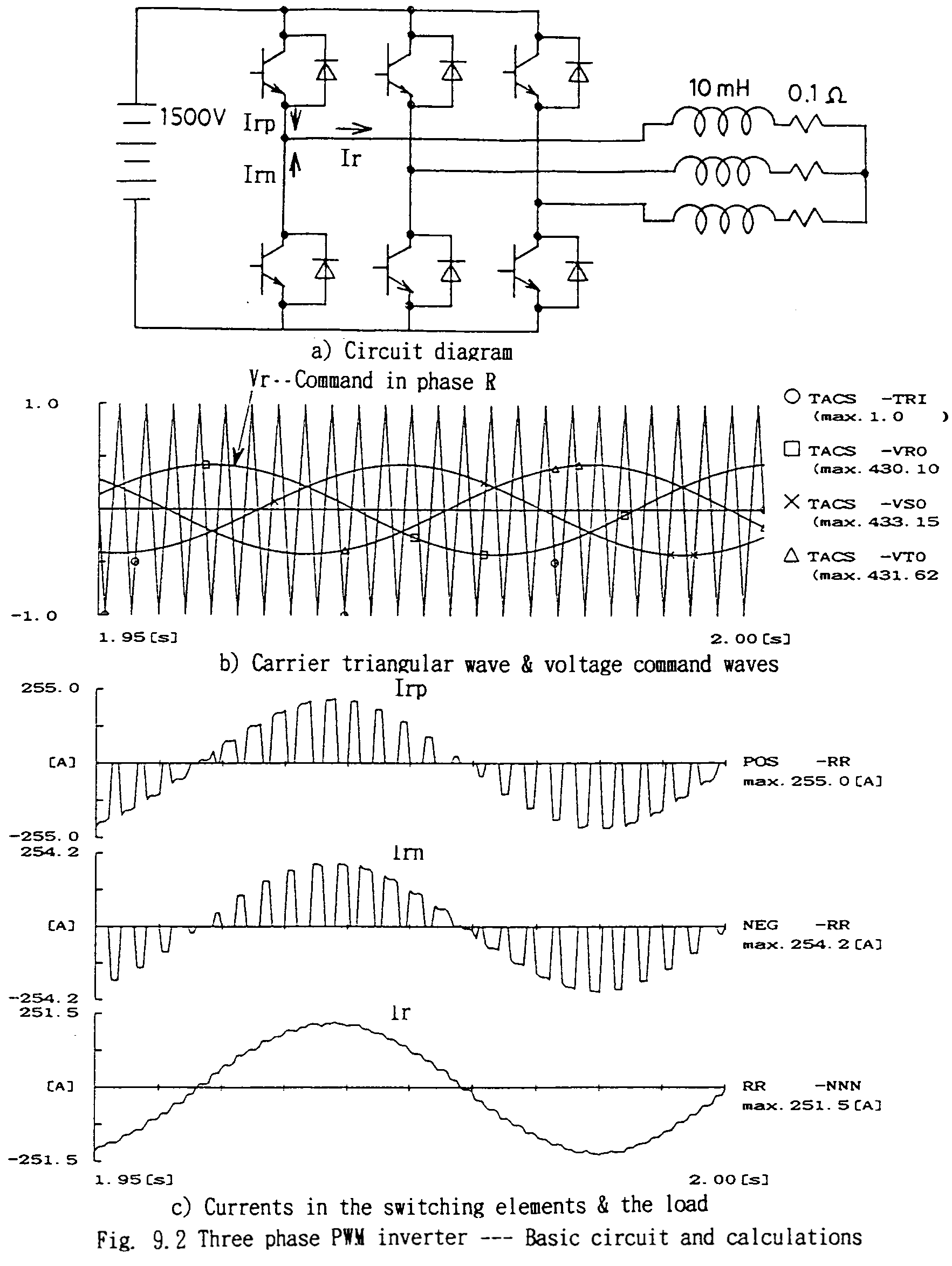
Owing to the development of power electronics technology, for the purpose of VVVF source, inverters with pulse width modulation (PWM) principle are mostly applied. Fig. 9.2 shows the principle of three phase PWM circuit and the performances. These are calculated results by EMTP. Three phase of mainly reactive load circuit is connected to a DC source via switching elements (Fig. 9.2 a)). The switching elements shall have bipolar characteristics, therefore, in case of applying thyristors, diodes of reversed polarities shall be connected in parallel to the thyristors as shown in the figure. In mainly reactive circuit, the current is dominated by the average value of the voltage applied, i.e., the product the rate of switch-on time intervals of the switching element and the DC source voltage. Fig. 9.2 b) shows the basic triangular wave-forms and the sinusoidal command waveforms corresponding to the three phase driving ac voltages. By the comparison of the instantaneous values of the triangular wave and the sinusoidal waves, during the values sinusoidal waves are higher than the triangular ones, the plus side elements are switched on and the minus side off. The following figures show the switch elements' currents and the load circuit current for one phase. The load current is mostly lagging by 90 deg. to the sinusoidal command wave corresponding to the driving voltage. Theoretically, as higher the triangular wave (carrier) frequency is, as less the harmonics components in the load current exists. The limitation depends on the switching element's performance.
