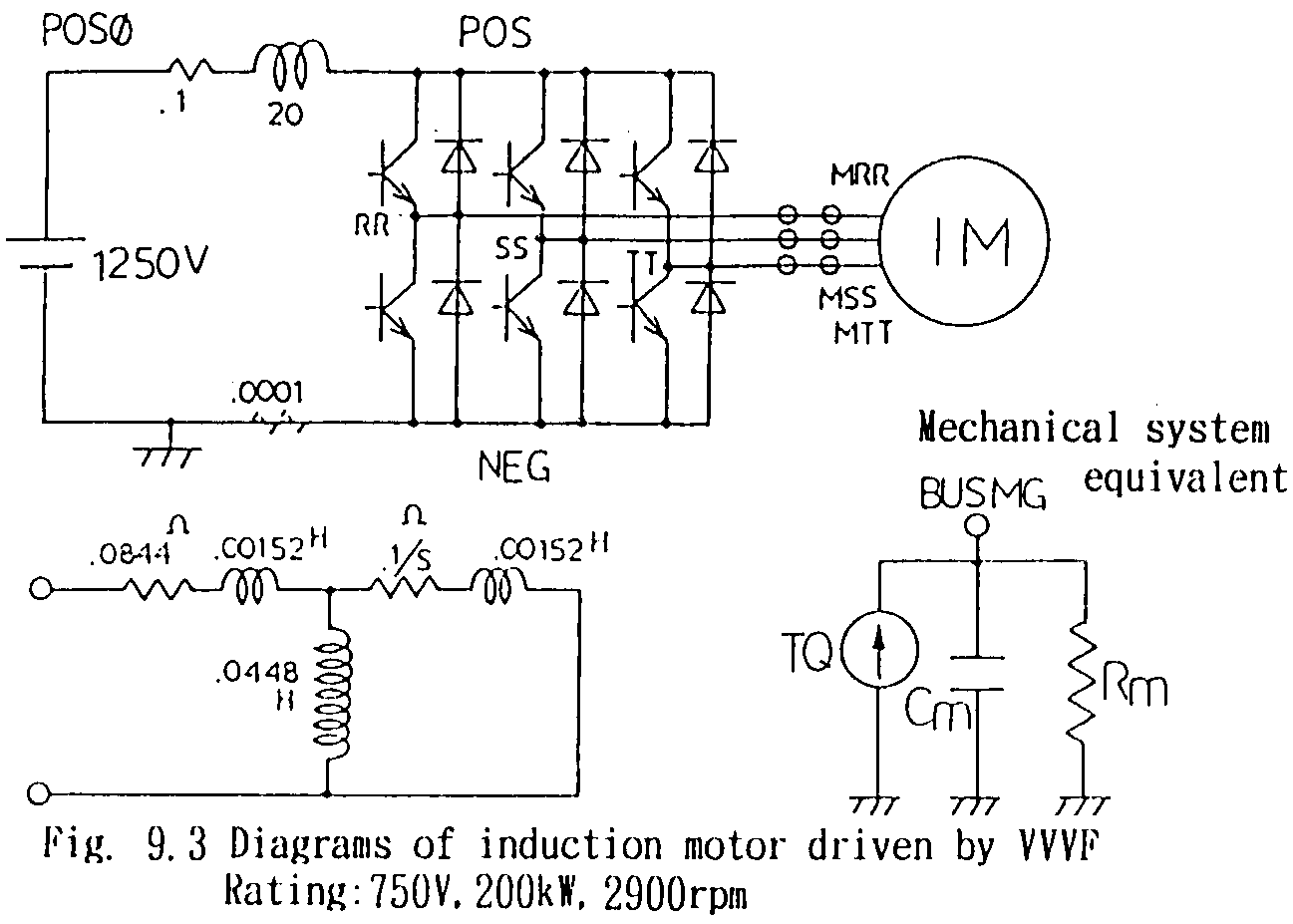
Fig. 9.3 shows circuit diagram, machine equivalent circuit and machine's mechanical system equivalent circuit which is applicable to EMTP calculation. Some characters in the figure are used as node names in EMTP data. The machine is modeled by "Universal Machine" in EMTP. For details of the modellings, see ATP Data Source attached.
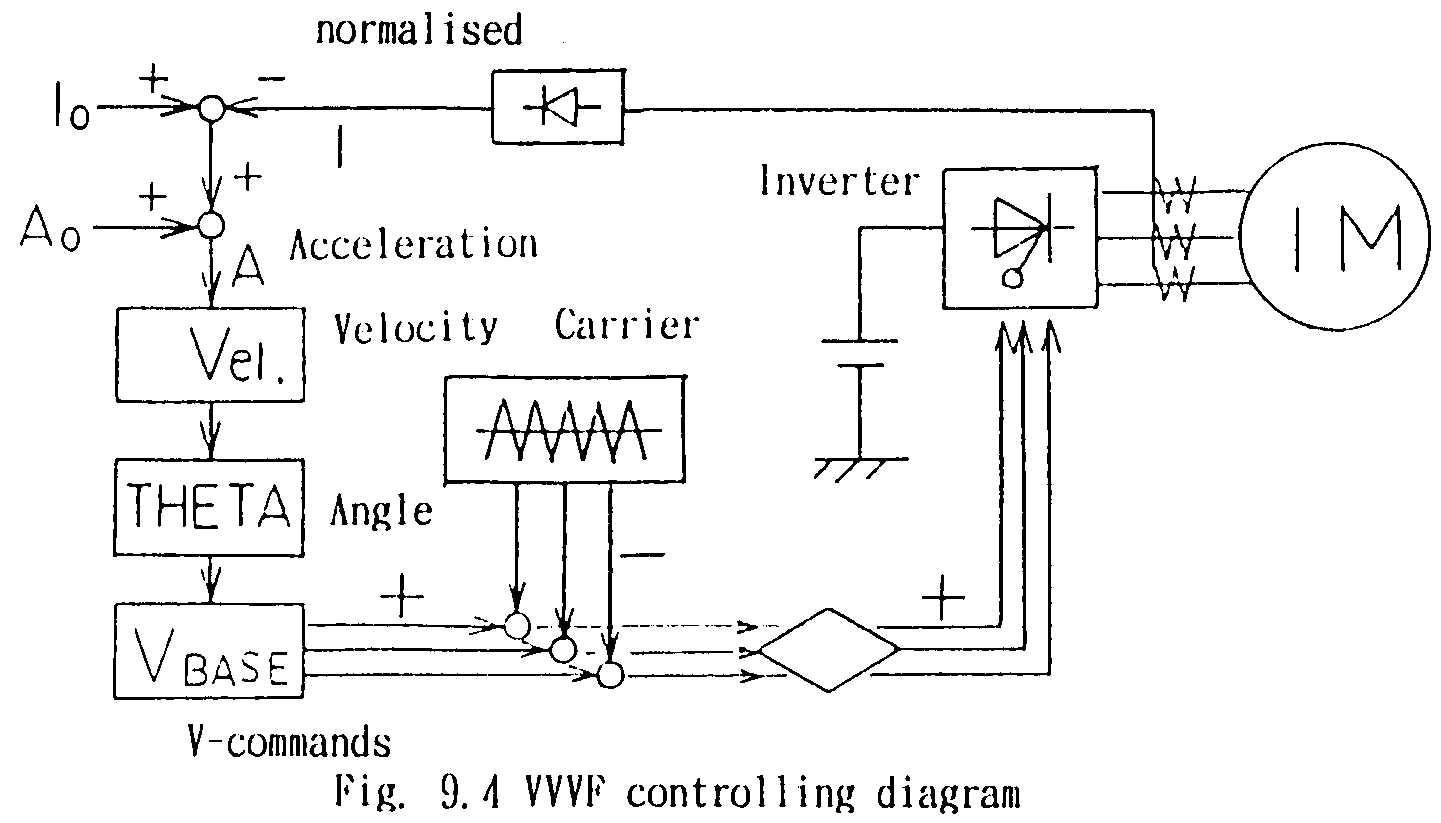
The VVVF source controlling principle is shown in Fig. 9.4 as a diagram. Imaging a starting train, then the process is:
- From the equations above, keeping E0/w and I1 to be constant, a constant starting torque T is obtained irrespective of the speed(w-ws).
- From the principle characteristics of the induction machine, higher acceleration corresponds to higher current I1. So, increasing w with constant E0/w and I1, constant torque and acceleration are obtained. These principles are applied to the sinusoidal command waves.
- For creating the gate signals of the thyristors, firstly triangular wave of carrier frequency (500 Hz) is created by integrating a square wave form in TACS of EMTP. Then, comparing the sinusoidal waves above shown and the triangular wave, gate signals are created.
- By the signals, thyristor elements are switched on/off and the motor is driven according to the VVVF principle shown in Sub-chapter 9.2 and Fig. 9.2.
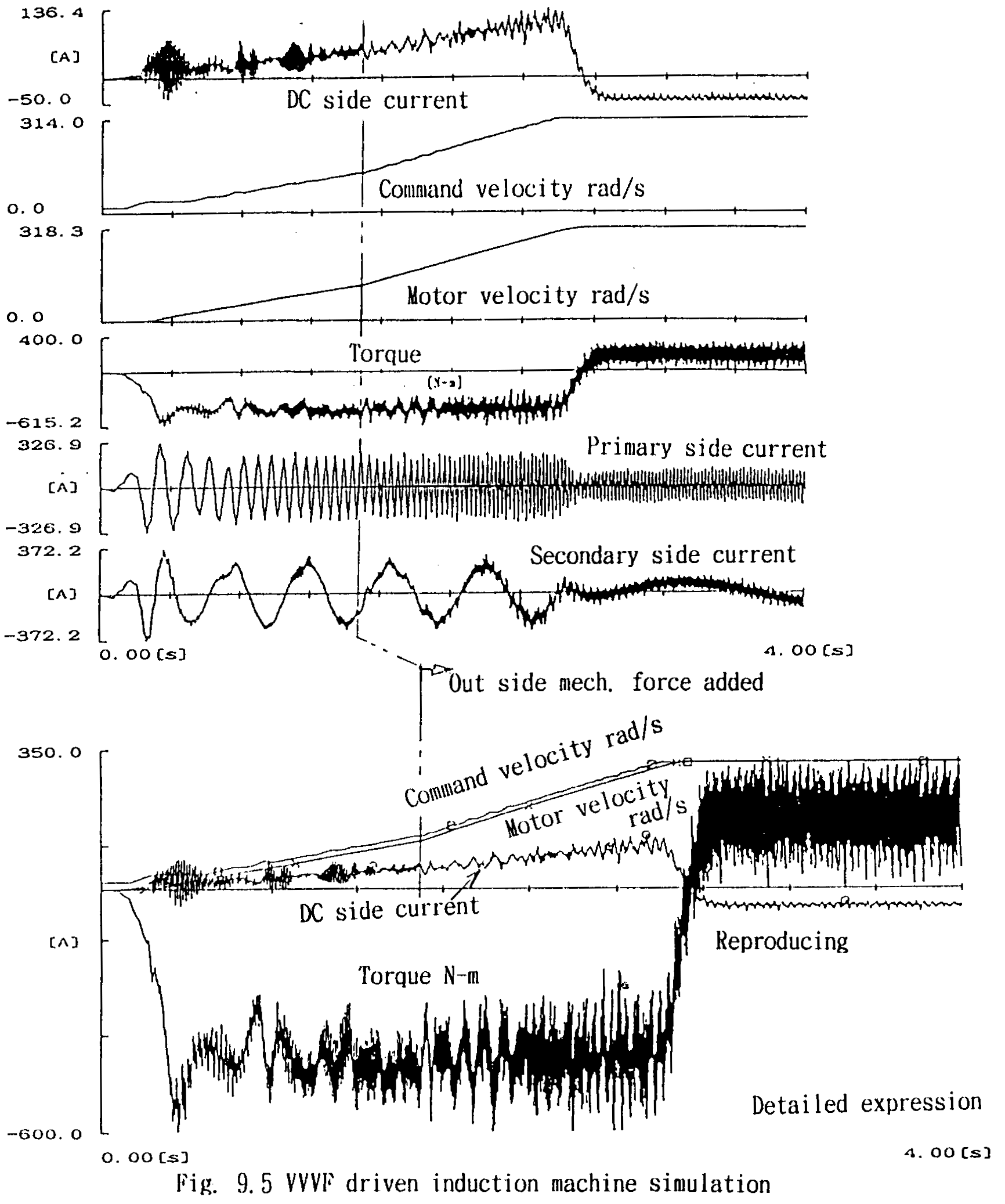
- In the calculation, at t = 1.5s, outside mechanical force of accelerating direction is applied, such as going down a slope, so the acceleration rate becomes higher.
- Finally, the source frequency is limited to 314 rad/s (specified), and due to the outside mechanical force, the machine is operated with a little higher speed than the specified one. The situation is "Reproducing electric power" and the slip value is minus. Also the torque and the DC side current are reversed.
- For creating the gate signals of the thyristors, firstly triangular wave of carrier frequency (500 Hz) is created by integrating a square wave form in TACS of EMTP. Then, comparing the sinusoidal waves above shown and the triangular wave, gate signals are created.
Calculated results and EMTP data are attached.
 ATP Data Source